Published
- 7 min read
CPE241 Week 4
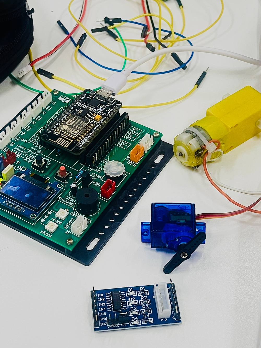
Actuators
-
Definition: Actuators are devices that take signals or commands from a control system and convert them into physical action or movement.
-
Function: Actuators execute commands to change the state of a system based on the input received, such as moving a part, opening a valve, or adjusting a position.
Examples:
- Electric Motor: Converts electrical energy into rotational motion.
- Solenoid: Uses an electromagnetic field to create linear motion.
- Hydraulic Actuator: Uses hydraulic fluid to produce movement in a hydraulic system.
Piezo Speaker
A piezo speaker is a type of transducer that converts electrical signals into sound. When used with an ESP8266 microcontroller, it can be employed to generate various audio tones, alerts, or even simple melodies.
Project 1
       #define spkPin D8
void setup() {
  pinMode(spkPin, OUTPUT);
}

void loop() {
  digitalWrite(spkPin, 1);
  delayMicroseconds(300);
  digitalWrite(spkPin, 0);
  delayMicroseconds(200);
}
Project 2
       #define spkPin D8
void setup() {
  pinMode(spkPin, OUTPUT);
}

void loop() {
  tone(spkPin, 262, 500);
  delay(600);
  tone(spkPin, 294, 500);
  delay(600);
  tone(spkPin, 330, 500);
  delay(600);
  tone(spkPin, 349, 500);
  delay(600);
  noTone(spkPin);
  delay(2000);
}
Side Project
To play the “Happy Birthday” tune using a piezo speaker with an ESP8266, you can use the tone() function to generate the appropriate frequencies and durations.
       #define piezoPin D8; // Pin connected to the piezo speaker

// Note frequencies in Hz for "Happy Birthday"
const int notes[] = {
  262, 262, 294, 262, 349, 330, // Happy Birthday to You
  262, 262, 294, 262, 392, 349, // Happy Birthday to You
  262, 262, 523, 440, 349, 330, 294, // Happy Birthday Dear [Name]
  466, 466, 440, 349, 392, 349 // Happy Birthday to You
};

// Durations of notes (in milliseconds)
const int durations[] = {
  500, 500, 1000, 1000, 1000, 2000, // Happy Birthday to You
  500, 500, 1000, 1000, 1000, 2000, // Happy Birthday to You
  500, 500, 500, 500, 500, 500, 500, // Happy Birthday Dear [Name]
  500, 500, 500, 500, 1000, 2000 // Happy Birthday to You
};

void setup() {
  pinMode(piezoPin, OUTPUT);
}

void loop() {
  int numNotes = sizeof(notes) / sizeof(notes[0]);
  for (int i = 0; i < numNotes; i++) {
    tone(piezoPin, notes[i]); // Play note
    delay(durations[i]); // Wait for the note to finish
    noTone(piezoPin); // Stop the note
    delay(50); // Short pause between notes
  }

  // Loop the song every 10 seconds
  delay(10000);
}
Project 3
OLED
Adafruit GFX
Adafruit SSD1306
       #include <Wire.h>
#include <Adafruit_GFX.h>
#include <Adafruit_SSD1306.h>

Adafruit_SSD1306 OLED(-1);

void setup() {
  OLED.begin(SSD1306_SWITCHCAPVCC, 0x3C);
}

void loop() {
  OLED.clearDisplay();
  OLED.setTextColor(WHITE);
  OLED.setCursor(0, 0);
  OLED.setTextSize(1);
  OLED.println("CPE241");
  OLED.setCursor(0, 10);
  OLED.setTextSize(2);
  OLED.println("I O T");
  OLED.display(); //
}
Project 4
RGB LED
Library : Adafruit NeoPixel
Adafruit_NeoPixel(NUMSLEDs, PINSLEDs, NEO_GRB + NEO_KHZ800);
- NUMSLEDs: Number of LEDs
- PINSLEDs: Pin number to which the LED strip is connected on the NodeMCU
- NEO_GRB + NEO_KHZ800: Type of LED pixel (GRB color order and 800 KHz signal frequency)
       #include <Adafruit_NeoPixel.h>

#define NUMSLEDs 2
#define PINSLEDs 10

Adafruit_NeoPixel SLEDs = Adafruit_NeoPixel(NUMSLEDs, PINSLEDs, NEO_GRB + NEO_KHZ800);

void setup() {
  SLEDs.begin();
  SLEDs.show();
  SLEDs.setBrightness(255);
}

void loop() {
  SLEDs.setPixelColor(0, SLEDs.Color(0 , 0 , 0));
  SLEDs.setPixelColor(1, SLEDs.Color(0, 0, 0));
  SLEDs.show();
}
To set colors in NeoPixels using the RGB format, you use the SLEDs.Color() function provided by the Adafruit NeoPixel library. The function accepts three parameters representing the Red, Green, and Blue components of the color. Here’s how to use this function with an explanation of the RGB format:
RGB Color Format
- Red ( R ): Controls the intensity of red in the color (0 to 255).
- Green ( G ): Controls the intensity of green in the color (0 to 255).
- Blue ( B ): Controls the intensity of blue in the color (0 to 255).
Color Setting with SLEDs.Color()
SLEDs.Color(R, G, B): Sets the color of an LED using RGB values.R(Red) is the intensity of the red color.G(Green) is the intensity of the green color.B(Blue) is the intensity of the blue color.
The function SLEDs.setBrightness(50); sets the brightness of the LEDs to the specified value. Here’s a description in English:
SLEDs.setBrightness(50);: This function sets the brightness of the NeoPixels. The brightness value is specified between 0 and 255, where 0 is off (no light) and 255 is full brightness. In this case,50represents a dimmer brightness level.
Project 5
       #define B1A D1
#define B1B D2
#define A1A D6
#define A1B D7

void setup() {
  pinMode(B1A, OUTPUT);
  pinMode(B1B, OUTPUT);
  pinMode(A1A, OUTPUT);
  pinMode(A1B, OUTPUT);
}

void loop() {
  digitalWrite(B1A, HIGH);
  digitalWrite(B1B, HIGH);
//  digitalWrite(A1A, HIGH);
  analogWrite(A1A, 1000);
  digitalWrite(A1B, LOW);
}
You can change speed motor with analogWrite(A1A, 1000);
Project 6
Servo motor SG90
- Can rotate 90° - 180° (depending on the model)
- Operating Voltage: 5V
- Rotation control using PWM
       #include <Servo.h>

Servo myservo; // Create a servo object to control the Servo

void setup() {
  myservo.attach(2); // Attach the servo to GPIO2 (D4)
}

void loop() {
  myservo.write(0); // Rotate the Servo to 0 degrees
  delay(1000);
  myservo.write(45); // Rotate the Servo to 45 degrees
  delay(1000);
  myservo.write(90); // Rotate the Servo to 90 degrees
  delay(1000);
}
Project 7
Stepper Motor
Rated voltage : 5VDC
- Number of Phase 4
- Speed Variation Ratio 1/64
- Stride Angle 5.625° /64
Controlling a Stepper Motor
- 1 Phase - Full Step: Efficient in terms of power consumption.
- 2 Phase - Full Step: Provides higher torque and speed compared to the 1 Phase method.
- Half Step: Combines the functionality of both 1 Phase and 2 Phase stepping. It allows for finer resolution and smoother rotation.
1 Phase - Full Step
       #define In1 D1 // Red wire - pin 4
#define In2 D2 // Yellow wire - pin 3
#define In3 D3 // Green wire - pin 2
#define In4 D4 // Blue wire - pin 1

int motorSpeed = 4; // Define delay time

void setup() {
  pinMode(In1, OUTPUT);
  pinMode(In2, OUTPUT);
  pinMode(In3, OUTPUT);
  pinMode(In4, OUTPUT);
}

void loop() {
  // Step 1
  digitalWrite(In1, LOW);
  digitalWrite(In2, LOW);
  digitalWrite(In3, LOW);
  digitalWrite(In4, HIGH);
  delay(motorSpeed);

  // Step 2
  digitalWrite(In1, LOW);
  digitalWrite(In2, LOW);
  digitalWrite(In3, HIGH);
  digitalWrite(In4, LOW);
  delay(motorSpeed);

  // Step 3
  digitalWrite(In1, LOW);
  digitalWrite(In2, HIGH);
  digitalWrite(In3, LOW);
  digitalWrite(In4, LOW);
  delay(motorSpeed);

  // Step 4
  digitalWrite(In1, HIGH);
  digitalWrite(In2, LOW);
  digitalWrite(In3, LOW);
  digitalWrite(In4, LOW);
  delay(motorSpeed);
}
2 phase - Full Step
       #define In1 D1 // Red wire - pin 4
#define In2 D2 // Yellow wire - pin 3
#define In3 D3 // Green wire - pin 2
#define In4 D4 // Blue wire - pin 1

int motorSpeed = 4; // Define delay time in milliseconds

void setup() {
  pinMode(In1, OUTPUT);
  pinMode(In2, OUTPUT);
  pinMode(In3, OUTPUT);
  pinMode(In4, OUTPUT);
}

void loop() {
  // Step 1
  digitalWrite(In1, LOW);
  digitalWrite(In2, LOW);
  digitalWrite(In3, HIGH);
  digitalWrite(In4, HIGH);
  delay(motorSpeed);

  // Step 2
  digitalWrite(In1, LOW);
  digitalWrite(In2, HIGH);
  digitalWrite(In3, HIGH);
  digitalWrite(In4, LOW);
  delay(motorSpeed);

  // Step 3
  digitalWrite(In1, HIGH);
  digitalWrite(In2, HIGH);
  digitalWrite(In3, LOW);
  digitalWrite(In4, LOW);
  delay(motorSpeed);

  // Step 4
  digitalWrite(In1, HIGH);
  digitalWrite(In2, LOW);
  digitalWrite(In3, LOW);
  digitalWrite(In4, HIGH);
  delay(motorSpeed);
}
Half Step
       #define In1 D1 // Red wire - pin 4
#define In2 D2 // Yellow wire - pin 3
#define In3 D3 // Green wire - pin 2
#define In4 D4 // Blue wire - pin 1

int motorSpeed = 4; // Define delay time

void setup() {
  pinMode(In1, OUTPUT);
  pinMode(In2, OUTPUT);
  pinMode(In3, OUTPUT);
  pinMode(In4, OUTPUT);
}

void loop() {
  // Step 1
  digitalWrite(In1, LOW);
  digitalWrite(In2, LOW);
  digitalWrite(In3, LOW);
  digitalWrite(In4, HIGH);
  delay(motorSpeed);

  // Step 2
  digitalWrite(In1, LOW);
  digitalWrite(In2, LOW);
  digitalWrite(In3, HIGH);
  digitalWrite(In4, HIGH);
  delay(motorSpeed);

  // Step 3
  digitalWrite(In1, LOW);
  digitalWrite(In2, LOW);
  digitalWrite(In3, HIGH);
  digitalWrite(In4, LOW);
  delay(motorSpeed);

  // Step 4
  digitalWrite(In1, LOW);
  digitalWrite(In2, HIGH);
  digitalWrite(In3, HIGH);
  digitalWrite(In4, LOW);
  delay(motorSpeed);

  // Step 5
  digitalWrite(In1, LOW);
  digitalWrite(In2, HIGH);
  digitalWrite(In3, LOW);
  digitalWrite(In4, LOW);
  delay(motorSpeed);

  // Step 6
  digitalWrite(In1, HIGH);
  digitalWrite(In2, HIGH);
  digitalWrite(In3, LOW);
  digitalWrite(In4, LOW);
  delay(motorSpeed);

  // Step 7
  digitalWrite(In1, HIGH);
  digitalWrite(In2, LOW);
  digitalWrite(In3, LOW);
  digitalWrite(In4, LOW);
  delay(motorSpeed);

  // Step 8
  digitalWrite(In1, HIGH);
  digitalWrite(In2, LOW);
  digitalWrite(In3, LOW);
  digitalWrite(In4, HIGH);
  delay(motorSpeed);
}
Library stepper
To control a stepper motor in half-step mode using the Stepper library in Arduino, you’ll need to use the Stepper library and set up the motor to step through half steps.
       #include <Stepper.h>

const int stepsPerRev = 2048;
Stepper myMotor = Stepper(stepsPerRev, D1, D3, D2, D4);

void setup() {
  myMotor.setSpeed(10);
}

void loop() {
  myMotor.step(500);
  delay(500);
  myMotor.step(-500);
  delay(500);
}