Published
- 4 min read
CPE241 Week 3
Sensors and actuators
Sensors and actuators are fundamental components in various systems, especially in automation, robotics, and electronics. Here’s a brief overview of each:
Sensors
-
Definition: Sensors are devices that detect and measure physical properties or environmental conditions and convert them into signals or data that can be read and interpreted by other systems.
-
Function: Sensors collect information about the surrounding environment or the status of a system. They can measure a wide range of variables such as temperature, pressure, light, motion, humidity, and more.
Examples:
- Temperature Sensor: Measures temperature and converts it into an electrical signal.
- Proximity Sensor: Detects the presence or absence of an object within a certain range.
- Light Sensor: Measures light intensity and provides data that can be used to adjust lighting systems.
Actuators
-
Definition: Actuators are devices that take signals or commands from a control system and convert them into physical action or movement.
-
Function: Actuators execute commands to change the state of a system based on the input received, such as moving a part, opening a valve, or adjusting a position.
Examples:
- Electric Motor: Converts electrical energy into rotational motion.
- Solenoid: Uses an electromagnetic field to create linear motion.
- Hydraulic Actuator: Uses hydraulic fluid to produce movement in a hydraulic system.
Relationship Between Sensors and Actuators
- Sensors provide the data or feedback that informs the control system about the current state or conditions of a system.
- Actuators perform actions based on the control signals or commands derived from sensor data.
In a typical automated system, sensors gather information about the environment or system state, and this data is processed by a controller. The controller then sends commands to actuators to perform specific actions, thereby adjusting or controlling the system as needed.
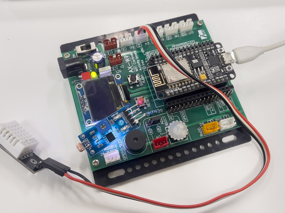
Project 1
DHT22
Pinout of DHT22:
- VCC: Connect to 5V
- GND: Connect to GND
- DATA: Connect to a digital pin on the borad (e.g., pin 2)
- NC: No connection (this pin is not used)
Install the DHT Sensor Library:
- Go to the Arduino IDE.
- Navigate to Sketch > Include Library > Manage Libraries.
- Search for DHT sensor library by Adafruit and install it.
- Search for Adafruit Unified Sensor by Adafruit and install it.
       #include "DHT.h"

#define DHTPIN D4
#define DHTTYPE DHT22

DHT dht(DHTPIN, DHTTYPE);

void setup() {
  Serial.begin(115200);
  dht.begin();
}

void loop() {
  float h = dht.readHumidity();
  float t = dht.readTemperature();
  float f = dht.readTemperature(true);

  Serial.print("Humidity: ");
  Serial.print(h);
  Serial.print("% Temperature: ");
  Serial.print(t);
  Serial.print("°C ");
  Serial.print(f);
  Serial.println("°F");

  delay(2000);

}
Project 2
HR-SR04 Ultrasonic Sensors
Pinout of HC-SR04
- VCC: Connect to 5V
- GND: Connect to GND
- TRIG: Trigger pin to send the pulse
- ECHO: Echo pin to receive the pulse
       #define trigPin D4
#define echoPin D3

long duration;
long distance;

void setup() {
  pinMode(trigPin, OUTPUT);
  pinMode(echoPin, INPUT);
  Serial.begin(115200);
}

void loop() {
  digitalWrite(trigPin, LOW);
  delayMicroseconds(2);
  digitalWrite(trigPin, HIGH);
  delayMicroseconds(10);
  digitalWrite(trigPin, LOW);

  duration = pulseIn(echoPin, HIGH);
  distance = duration / 58;

  Serial.print("Distance : ");
  Serial.println(distance);
  delay(2000);
}
Project 3
LDR Light sensor analog
Pin of LDR :
- One side of the LDR goes to 3.3V (VCC) of the ESP8266.
- One side of the fixed resistor connects to the GND (Gnd) pin on the ESP8266.
- The other side of the LDR connects to one side of the fixed resistor and also to the Analog input pin (A0) of the ESP8266.
       #define LDR A0

void setup() {
  pinMode(LDR, INPUT);
  Serial.begin(115200);
}
void loop() {
  int dt;
  dt = analogRead(LDR);
  Serial.print("intensity = ");
  Serial.println(dt);

  delay(1000);
}
Project 4
Light Sensor BH1750
Pin of Connections for BH1750
- VCC to 3.3V (or 5V if your sensor supports it, but using 3.3V is safer for the ESP8266).
- GND to GND on the ESP8266.
- SDA to D2 (GPIO4) on the ESP8266.
- SCL to D1 (GPIO5) on the ESP8266.
Install the DHT Sensor Library:
- Go to the Arduino IDE.
- Navigate to Sketch > Include Library > Manage Libraries.
- Search for BH1750 by Christopher Laws and install it.
       #include <Wire.h>
#include <BH1750.h>

BH1750 lightMeter;

#define SDA D2
#define SCL D1

void setup() {
  Serial.begin(115200);
  Wire.begin(SDA, SCL);
  lightMeter.begin();
}
void loop() {
  float lux = lightMeter.readLightLevel();
  Serial.print("Light: ");
  Serial.print(lux);
  Serial.println(" lx");
  delay(1000);
}
Compare
LDR Light sensor analog vs BH1750
       #include <Wire.h>
#include <BH1750.h>
BH1750 lightMeter;

#define SDA D2
#define SCL D1
#define LDR A0

void setup() {
  pinMode(LDR, INPUT);
  Serial.begin(115200);
  Wire.begin(SDA, SCL);
  lightMeter.begin();
}
void loop() {
  int dt;
  dt = analogRead(LDR);
  Serial.print("dt = ");
  Serial.print(dt);

  float lux = lightMeter.readLightLevel();
  Serial.print(" ,Lux: ");
  Serial.println(lux);


  delay(1000);
}